B.S. Mechanical Engineering, Minor in Mathematics
Northeastern University
Semi-Autonomous Research Vessel

For my senior capstone project at Northeastern, my group was tasked with designing a vessel that was both "waveproof" and autonomous.
I led the design of the vessel's electrical architecture, which included the propulsion, steering, control and navigation systems. As an avid sailor, I also advised on hull design and waterproofing techniques.
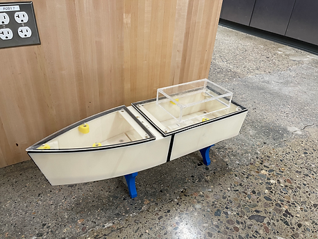
Pictured Below: Our first hull iteration was printed in ABS plastic in two separate 14 inch sections. We then bonded them together using acetone and sealed the hull with a popular liquid rubber coating.


We then used this first hull iteration to test our flywheel stabilization theory, shown in the leftmost video. We noted a significant resistance to roll from perturbations which confirmed our flywheel theory. This was followed with testing of the steering system and assembly of the electrical architecture which includes:
-
5600 mAh Lithium Polymer Battery
-
30 Amp Water Cooled Electronic Speed Controller
-
4900 kV Brushless Inrunner Motor
-
12.5 gram Digital Metal Gear Servo
-
Pixhawk Flight Controller running ArduPilot
-
Turnigy 6 Channel Transmitter + Receiver
-
915 MHz Telemetry Tx/Rx
-
Ublox M8N GPS Module


After modifying our initial hull design to accommodate the electronics I had selected and adding standoffs and inserts to allow for an acrylic lid to be screwed on over gasket tape to seal the internal hull volume, we began testing the vessel in Northeastern's pool. Here we were able to put numbers to our flywheel stabilization theory and test our propulsion and steering systems as well as the boat's ability to self-right if capsized.


Stabilization with flywheel active
Propulsion testing
Rack and pinion steering system

The biggest takeaway from our pool tests were the evidence of significant reduction in roll angle when subjected to waves. With the flywheel stabilization OFF, the average roll angle from an incident wave was about 8 degrees. With stabilization ON and given sufficient time for the flywheel to spin up, this was reduced to about 1-2 degrees, resulting in a roll reduction to incident waves of more than 75%.
With this critical test completed, we pushed on to create a third hull iteration, and I readied the autonomy system by achieving our first GPS lock and simulating waypoint missions using the Mission Planner desktop application that pairs with ArduPilot firmware running on the Pixhawk flight controller.
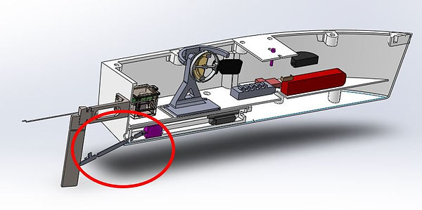
Proposed vessel layout for V3

V3 hull design offering a removable forward lid to improve access to hull interior

Propulsion testing revealed that the propeller would breach the surface of the water, causing a significant loss in thrust. I advised angling the prop shaft down to ensure the propeller would be fully underwater for maximum efficiency.
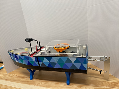
The V3 hull design after printing and assembly:


Open water testing and new paint job
Capstone Day!
